Are you struggling to translate your intricate 3D models into real-world constructions? Discover the transformative power of “Planarization of Meshes,” a cutting-edge technique that seamlessly converts complex, non-planar surfaces into flat, constructible elements.
Dive into our latest blog post to unlock the secrets of efficiently bridging the gap between digital design and physical fabrication, enabling you to bring even the most ambitious architectural visions to life.
Table of Contents
What is Meshes in Grasshopper?
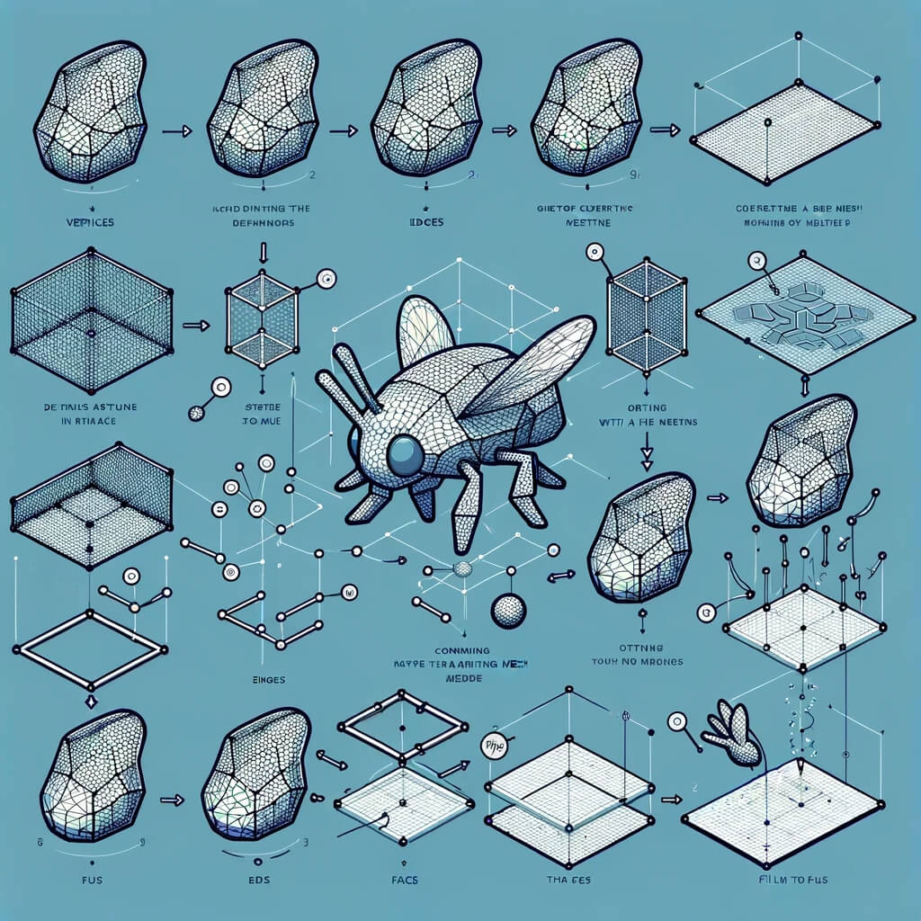
Meshes in Grasshopper, which is a part of Rhino’s 3D modeling software, refer to a type of geometry that is used for creating complex three-dimensional shapes. Unlike NURBS (Non-Uniform Rational B-Splines) geometry, which uses curves and surfaces to define shapes, meshes are composed of vertices, edges, and faces to form a polygonal representation of 3D objects.
Here are some key points about meshes in Grasshopper:
- Vertices: The points in 3D space that define the corners of the mesh.
- Edges: The lines connecting the vertices.
- Faces: The flat surfaces bounded by edges. In Grasshopper, faces are usually triangular or quadrilateral, though more complex polygons can also be used.
- Flexibility and Efficiency: Meshes are particularly useful for representing complex forms, including organic shapes, terrain models, and facades, with a high level of detail. They tend to be more memory efficient than NURBS when dealing with very complex models.
- Analysis and Manipulation: Grasshopper provides a wide range of tools for analyzing and manipulating meshes. This includes operations like subdivision, smoothing, mesh reduction, and morphing.
- Applications: Meshes are widely used in various fields including architecture, industrial design, game development, and animation. They are especially valued for rapid prototyping, digital fabrication (such as 3D printing), and visualization.
- Interoperability: Mesh data can be easily shared with other software tools and platforms, making it a versatile format for complex modeling tasks that require the use of multiple software solutions.
In Grasshopper, working with meshes involves using specific components designed for mesh creation, manipulation, and analysis. Users can generate meshes programmatically, allowing for a high degree of customization and control over the final geometry.
This makes Grasshopper a powerful tool for designers and engineers looking to explore complex forms and structures.
How do you make a Grasshopper mesh?
Creating a mesh in Grasshopper involves using specific components designed to construct and manipulate mesh geometry. This process can vary in complexity depending on the form and level of detail you’re aiming for. Here’s a straightforward guide to get you started with mesh creation:
1. Start Rhino and Grasshopper
Open Rhino and launch Grasshopper from the Rhino command line by typing Grasshopper.
2. Basic Mesh Components
Grasshopper has several components under the Mesh tab that are directly related to creating and manipulating meshes. For a basic mesh, you can start with these components:
- Mesh Primitives: These are components that generate simple mesh forms like planes, spheres, and boxes. You can find them under
Mesh>Primitive. - Construct Mesh: This component allows you to manually define a mesh by providing vertices (points) and face definitions (how vertices are connected to form faces). It’s located under
Mesh>Util.
3. Creating a Simple Mesh
To create a simple custom mesh, follow these steps:
a. Define Vertices
- Point Components: Use the
Pointcomponent (found underParams>Geometry) to create points that will serve as vertices of your mesh. - Construct Point: Alternatively, use the
Construct Pointcomponent to define points through coordinates.
b. Define Faces
- Faces are defined by indexing vertices. You need to tell Grasshopper how to connect the vertices to form faces. This is usually done through a panel where you input the indices of vertices that should be connected, starting from 0.
- For example, a triangular face connecting the first three vertices would be defined as
0, 1, 2.
c. Construct Mesh
- Mesh Component: Drag a
Construct Meshcomponent onto the canvas. - Connect Vertices: Connect your points (vertices) to the
Verticesinput of theConstruct Meshcomponent. - Define Faces: Connect a panel with your face definitions to the
Facesinput.
4. Advanced Mesh Creation
For more complex meshes, consider these approaches:
- From Surfaces: Use components like
Mesh SurfaceorMesh Brepto create meshes from NURBS surfaces or BReps. - Subdivision and Refinement: Tools like Weaverbird (a plugin) offer components for subdividing and smoothing meshes for more complex geometries.
- Kangaroo Physics: For dynamic mesh creation and manipulation, Kangaroo offers components for simulating physical behaviors and forces on meshes.
5. Visualizing the Mesh
Once the mesh is constructed, it will be visible in the Rhino viewport. You can further manipulate its appearance using Grasshopper’s display components or by adjusting Rhino’s display settings.
6. Plugins and Extensions
For more advanced mesh operations, consider using Grasshopper plugins like Weaverbird, Kangaroo, or LunchBox. These can significantly expand your capabilities for mesh creation and manipulation.
This guide provides a starting point for mesh creation in Grasshopper. As you become more familiar with the software, you’ll discover numerous ways to create and manipulate meshes for various applications, from architectural design to digital fabrication.

How to create a Polygons on Grasshopper?
Creating polygons in Grasshopper, the visual programming language integrated with Rhino 3D is a straightforward process thanks to its intuitive interface and component-based approach. Here’s a basic guide to creating polygons in Grasshopper:
1. Start Rhino and Grasshopper
First, ensure Rhino is running and then start Grasshopper from within Rhino. You can usually do this by typing Grasshopper into the Rhino command line.
2. Add a Polygon Component
- In Grasshopper, locate the
Polygoncomponent. You can find it under theCurvetab, within thePrimitivesub-category. - Drag the
Polygoncomponent onto the canvas. This component is responsible for creating regular polygons.
3. Specify the Center Point
- The
Polygoncomponent requires a center point. You can provide this by adding aPointcomponent (found underParams>Geometry) or by simply using theConstruct Pointcomponent for more control over the coordinates. - Connect the
Pointcomponent to theC(Center) input of thePolygoncomponent.
4. Specify the Radius
- You need to define the radius of the polygon. You can do this by adding a
Number Slidercomponent (found underParams>Input). - Adjust the number slider to your desired radius and connect it to the
R(Radius) input of thePolygoncomponent.
5. Specify the Number of Sides
- The number of sides of the polygon is also controlled by a
Number Slider. Create another number slider and set it to only allow integer values that represent the number of sides you want your polygon to have (for example, 3 for a triangle, 4 for a square, etc.). - Connect this slider to the
N(Sides) input of thePolygoncomponent.
6. Optional: Adjust Plane
- If you want your polygon to be oriented differently than the default XY plane, you can specify a different plane using the
Planecomponent. - Connect the
Planecomponent to theP(Plane) input of thePolygoncomponent if needed.
7. Preview the Polygon
- After connecting all necessary inputs, the polygon will be generated and displayed in the Rhino viewport. You can adjust the sliders in real time to see how changes affect the polygon.
8. Further Manipulation
- You can further manipulate or use the polygon by connecting the output of the
Polygoncomponent to other components in Grasshopper, enabling complex geometrical constructions and manipulations.
This basic workflow introduces you to creating and manipulating polygons in Grasshopper. The real power of Grasshopper lies in its ability to let you parametrically control and combine these basic elements into much more complex forms and operations, enabling a vast array of design possibilities.
How to Planarization of Meshes & Polygons on Grasshopper?
Planarization of meshes and polygons in Grasshopper is a critical step in computational design, especially in fields like architecture and industrial design, where you need to fabricate the designed forms. Planarization transforms non-planar faces into planar ones, making them easier to construct with real-world materials like glass, metal, or wood panels.
Here’s how you can approach the planarization of meshes and polygons in Grasshopper:
Basic Concepts
- Non-Planar Faces: These are polygonal faces where not all vertices lie on the same plane. In construction, non-planar faces pose a challenge since most building materials are flat.
- Planarization: This process modifies the geometry to make faces planar while trying to preserve the overall form as much as possible.
Tools and Techniques
- Kangaroo Physics: Kangaroo is a live physics engine for interactive simulation, form-finding, optimization, and constraint solving. It includes components for planarization.
- Weaverbird: Weaverbird is a topological modeler that contains many utilities, including mesh planarization tools. It’s great for refining meshes after the initial planarization.
Planarizing with Kangaroo Physics
To planarize a mesh or polygons in Grasshopper using Kangaroo, follow these general steps:
1. Set Up Your Geometry
- Import your mesh or polygons into Grasshopper. If starting from polygons, you might need to construct a mesh from them.
2. Kangaroo Planarization
- Load Kangaroo Components: You will need components like
Goal Objects,Solver, andPlanarizefrom the Kangaroo Library. - Planar Goal: Connect your mesh to a
Planargoal component. This defines the planarization as an objective for the Kangaroo solver. - Solver: The Kangaroo
Solvercomponent will take thePlanargoal as input and iteratively adjust your mesh to meet these goals. - Adjust Parameters: Depending on your specific needs, you might need to adjust the strength of the planarization goal or add other constraints.
3. Iteration
- The Kangaroo solver works iteratively. You will likely need to run the solver multiple times, tweaking parameters as you go, to achieve the desired level of planarization.
4. Additional Goals (Optional)
- For complex geometries, you might need to combine planarization goals with other constraints like edge lengths, angles, or specific surface characteristics to control the form.
5. Weaverbird for Refinement (Optional)
- After planarization with the Kangaroo, use Weaverbird to smooth and refine the mesh. This can help in achieving a more visually pleasing result or in preparing the geometry for fabrication.
Visualization and Evaluation
- Evaluate Planarity: Use Grasshopper’s analysis tools to evaluate the planarity of your faces after planarization.
- Adjust and Iterate: Based on your evaluation, you may need to adjust constraints and re-run the solver.
Final Steps
- Once satisfied with the planarization, you can proceed with further design development, detailing, or preparation for fabrication, using other tools within Rhino and Grasshopper.
Note
Planarization can be computationally intensive and might require trial and error to achieve the best results. It’s important to start with simple models to understand the effects of various parameters and constraints before moving on to more complex geometries.

Conclusion
The process of “Planarization of Meshes” plays a pivotal role in transforming complex geometries into fabricable designs, bridging the gap between digital modeling and physical construction.
By employing sophisticated algorithms and tools in Grasshopper, designers can efficiently convert non-planar faces into planar ones, ensuring their projects are not only visually compelling but also practically buildable.
This technological advancement underscores the importance of computational design in modern architecture and engineering, allowing for the creation of more intricate and innovative structures.


